|
Digital Instrument Cluster
A How-To Guide For The DIYer
I had been attempting to
work with Nordskog to build a digital instrument cluster for the
Probe but the company went under in the typical corporate
fashion. So I went looking to see if I could find a
suitable digital cluster which could be reasonably easy to
install. I found several possibilities such as the Ford
Tarus, Ford Windstar, Mercury Villager and Buick Riviera.
|
|
The Cluster:
I
chose the Mercury Villager cluster from the 1990's because as
seen to the right -it is very similar in size and shape.
Also it had the highest reading tachometer out of all the other
possibilities. It will go to 8k RPM which is a good limit
for our engines.
The
Villager is a 6-cylinder which makes it a good candidate because
the tach will read the correct RPM. Also -the temperature
sensor has the same signal output as our Probe sender
does. So the Tach and temperature are no-brainers.
|
 |
|
| The
How-To:
|
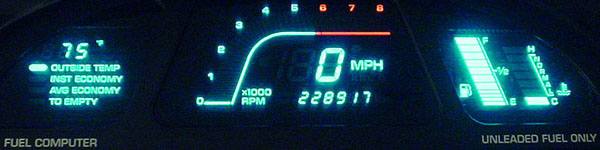
| Here is the Villager cluster
when lit up: |
 |
|
The Outside Air Temperatrue
(OAT) is a nice "gee-wiz" feature but is really
un-necessary and the KL cars do not have a fuel flow
signal from the ECU to make use of the fuel economy
computer function. So since the displays are
individual tubes it is easy to remove the un-needed
display to the far left. This will make room for
other more important guages such as oil pressure or O2
wideband, etc.
|
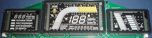 |
| Below is the main printed
circuit board (PCB) that does all of the calculations and
conversions for the displays. It is not necessary to
do any modifications to this board. |
 |
|
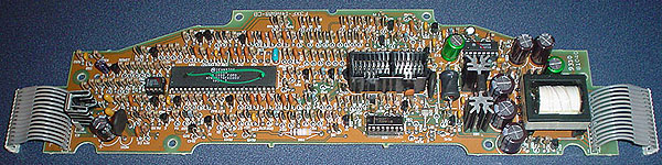
These are tools that you
would need to remove the un-needed display. The blue
thing is a solder sucker and works very good to remove the
molten solder from in the holes around the pins. You
can also use de-soldering braid to suck up some of the
solder.
|
 |
|
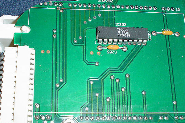
Here is the display board
with the tube removed. Notice how I filled the holes
with solder after the display tube was removed. This
is to keep the foil tracings connected from one side of
the board to the other. This is a dual sided PCB
-meaning that there are traces as seen in this photo below
-also on the reverse side but just with a different
layout. This is called very good usage of all
available real-estate. There are too many circuit
paths to be able to lay out the entire circuit on only one
side of a board so they also use the back side. If
you do not fill the holes after removing the tube then you
may be creating an open in a circuit that lights one of
the display tubes that you do want. So fill them
well. Also notice in the photo below how the corner
has been rouned off. This is for a clearance
issue. The last three holes on the left are only
used to help hold the tube in place. They do not
have any tracings on either side of the board so it
doesn't matter if you cut into them some as I have
done. Just be careful when rounding the corner that
you do not remove any tracings near by. The large
green areas are typically grounds and it doesn't hurt any
to cut into them some either.
|
 |
|
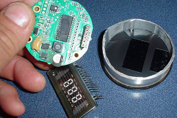
Here is a VFD type oil
pressure gauge and I have cut the casing carefully with a
Dremel and removed the display to mount it to the display
PCB while mounting the circular PCB shown somewhere
remotely with a ribbon cable connecting the two.
|
 |
|
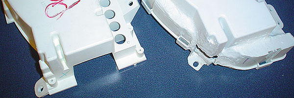
Now it is time to do some
plastic welding to join the PGT cluster housing and the
Villager one. I cut both pieces so that I have the
forward rim of the PGT cluster and the back shell of the
Villager since it has all of the mounts for the PCB's.
|
 |
|
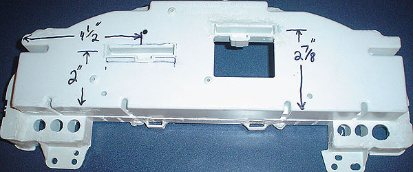
Here is the finished welded
shell with the PGT connector coves welded in place to make
it so that the stock PGT connectors will still plug into
it and keep it totally plug-n-play. The
measurements are for locations for the coves that miss all
essential electronic components inside the housing.
If you do not place the coves in these locations then you
could end up with some bent over components when you fully
assemble the unit.
|
 |
|
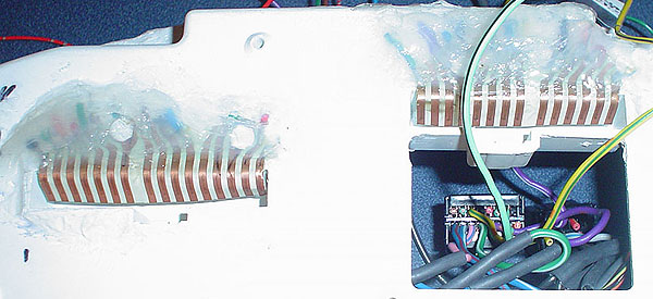
Here is how I melted some
stubs of plastic to hold in the foil traces from the back
side of the PGT cluster for soldering wires to. I
drilled small holes just to the ends of the foil traces
where it was cut so that the holes will stabilize the
wires. once you weld on this foil -the plastic
in-between WILL MELT! So after you have them all
soldered and the plastic is missing between them all then
you need to glue everything in place with silicone glue as
shown. This secures everything nicely and the PGT
plugs will now plug right in just as they did with the OEM
piece.
|
 |
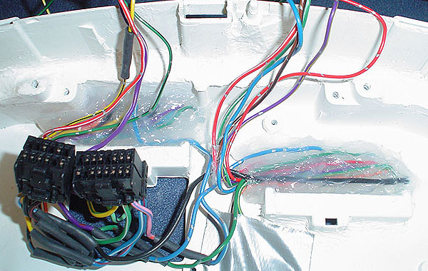
| Here is the inside view and
the Villager plugs when spliced in. They will
connect right up to the Villager PCB nicely inside the
housing. Click here
for the Villager wiring diagram. |
 |
|
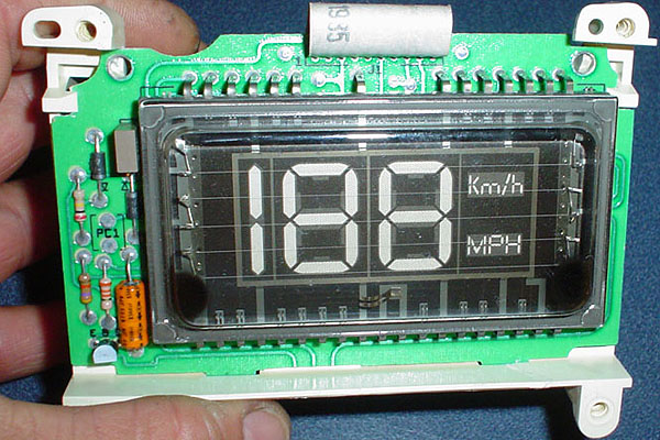
This is a VFD display for
speed only and it comes from an eighties model
Lincoln. I plan to make a Head Up Display HUD from
this one. A HUD is where the speed is
projected/reflected onto the windshield so that you can
see it in front of you without taking your eyes off the
road. Several newer cars are coming out with this
option.
|
 |
|
I have been running the
display for a while installed within the car. So far
- the test results are fantastic. It took a bit to
get the fuel tank sending unit tweaked for correct
readings but after that - it is so linear that it appears
to be more accurate than a stock Probe fuel guage.
The shot below was taken using a flash. The flash
goes through the 1/8 inch thick blue Plexiglas filter that
I have cut from a sheet and thus shows the display tubes
behind the filter. The Plexiglas must be cut with a
rotary drill type cutting tool. Any sawing type tool
will cause the Plexiglas to crack.
|
 |
|
This second photo was taken
without a flash to show more closely what the display
looks like (without the over-exposure blur of this
one). When you shoot a light source it can often
cause the blurring effect. But at least you can see
close to what it looks like here:
|
 |
|
These types of digital
clusters can be fit similarly into other cars such as the
Mazda MX6 or 626. I know of a few people who have
started a similar conversion for the 626 so when they are
done -perhaps we can post photos of those as well.
The numbers up in the top right hand corner are my oil
pressure.
|